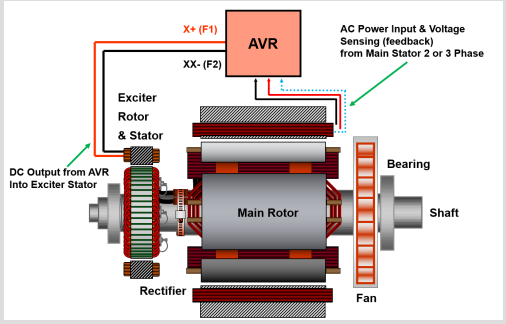
Excitation systems are the systems that supply field current to a alternator’s rotor winding. Excitation systems that are well-designed give operational dependability, stability, and quick transient response.
The four common excitation methods include:
- Shunt or Self Excited
- Excitation Boost System (EBS)
- Permanent Magnet alternator (PMG)
- Auxiliary Winding (AUX).
Each strategy has its own set of advantages. To deliver DC output to the exciter stator, all techniques employ an Automatic Voltage Regulator (AVR). The AC output of the exciter rotor is rectified to a DC input for the main alternator rotor. More complex systems employ a second AVR input. This article will go into the construction, function, and application of each technique, as well as contain diagrams and pictures.
Permanent Magnetic Alternator (PMG)
Permanent magnet alternators are among the most well-known individually excited techniques. On the driven end of the alternator shaft, a permanent magnet is installed.
When the alternator shaft spins, the PMG sends isolated power to the AVR. When delivering non-linear demands such as motor starting, the AVR makes use of the excess power.
When the alternator shaft rotates, a clean, isolated, and continuous 3-phase waveform is created.
The following are some of the advantages of employing alternators equipped with the PMG excitation method:
The excitation field does not collapse, allowing for the clearing of prolonged short circuit defects.
Changing the load has no effect on the excitation field.
Voltage is generated at first starting and is independent of residual magnetism in the field.
The excitation field does not collapse during motor start-up due to a lack of AVR supply.
The PMG System increases the size and weight of the alternator end. It is the most widely utilized excitation method for applications involving start-stop motors and other non-linear loads.


